Choosing a Host Interface for a 0.23-Inch Micro OLED in AR Glasses
In a pair of AR glasses the display interface is not a detail you settle after the optics. It decides how many conductors run through the temple, how much the driver IC has to buffer, and whether the panel can be refreshed fast enough that peripheral vision never catches a flicker. For a 0.23-inch 640x400 micro OLED at 60 Hz the raw payload is modest, roughly 15.4 million pixels per second before blanking, so the decision is rarely about bandwidth alone. It is about wire count, clock integrity, power per link, and how much of the timing you are willing to own in firmware. Serial links win on conductors, parallel links win on determinism, and the right answer follows from how much board area the temple actually gives you.
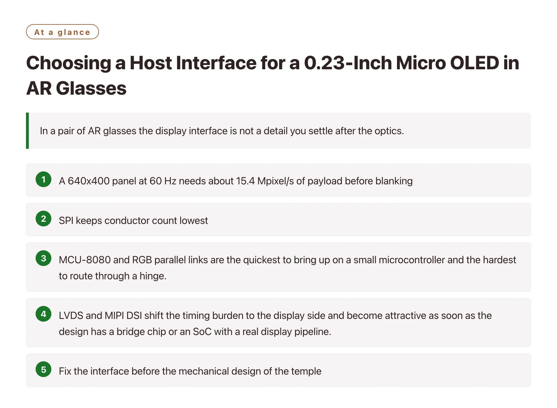
Key takeawaysA 640x400 panel at 60 Hz needs about 15.4 Mpixel/s of payload before blanking, which every candidate interface can carry; the differentiator is wiring and clocking, not throughput. · SPI keeps conductor count lowest, but frame buffering and refresh scheduling move into the host, which competes with sensors and radio work on the same processor. · MCU-8080 and RGB parallel links are the quickest to bring up on a small microcontroller and the hardest to route through a hinge. · LVDS and MIPI DSI shift the timing burden to the display side and become attractive as soon as the design has a bridge chip or an SoC with a real display pipeline. · Fix the interface before the mechanical design of the temple, because flex stiffness, connector height and shielding all follow from that decision.
Most teams pick a panel first, then discover that the interface they assumed is the one interface the chosen host cannot drive without an extra bridge. The cost of that discovery is not the bridge chip; it is the three weeks of re-spinning a flex that has to survive a hinge.
A 640x400 micro OLED is a small display with a small pixel clock, which makes it forgiving on bandwidth and unforgiving on everything else. Electrically it wants clean rails and a stable clock. Mechanically it wants few conductors and a thin cable. Firmware-wise it wants a timing owner.
This article walks through the five interface routes that customers realistically consider for near-eye glasses, what each one asks of the host, and a bring-up order that finds wiring and timing faults before the optics are glued in place.
What the link actually has to carry
The arithmetic is worth doing once. A 640x400 panel refreshed at 60 Hz consumes 640 x 400 x 60 pixels per second, about 15.4 million, and the physical link must also carry blanking intervals, so budget for noticeably more than that on the wire. This is a low figure by modern standards, which is why a four-wire serial link can plausibly drive it and why nobody should choose an interface purely on bandwidth.
What matters more is where the frame lives. Links that stream pixels continuously assume the source can produce a stable stream with correct timing at all times. Links that accept a frame and hold it let a small host assemble an image in its own memory and then hand it over, which is far easier to make robust when the same processor is also servicing an inertial sensor and a wireless stack. Panels in this class, such as the high brightness 0.23" Micro OLED display, are usually specified with a small set of supported modes, so read that list before drawing the block diagram rather than after.
Power per link is the third consideration and the one that is easiest to underestimate. Parallel links toggle many lines at once and can dominate the display's share of the power budget even when the panel itself is efficient, while low-voltage differential links cost a little static current and very little dynamic current.
Five realistic routes through a temple
| Interface | Where it fits best | What to verify before committing |
|---|---|---|
| SPI | Small hosts with little board area and moderate frame rates; the classic four-wire synchronous bus [1] | Effective throughput after command overhead, plus whether the host can sustain refresh while doing other work |
| MCU-8080 parallel | Microcontroller designs that already have a memory-style bus and want simple, deterministic writes | Pin count that must cross the hinge, and the write-strobe timing margin at the target clock |
| RGB parallel | Hosts with a dedicated LCD peripheral that outputs a continuous pixel stream | Pixel clock quality, setup and hold margins over flex length, and the emissions profile of many fast edges |
| LVDS | Designs that want a differential link with well understood skew and jitter behaviour [2] | Whether the panel or bridge accepts the lane count and mapping you plan to use |
| MIPI DSI | SoCs and bridges with a native display serial interface and a command or video mode pipeline | Lane count, clock frequency, and that the init sequence and mode set match the panel revision on the serial interface [4] |
Where each route actually hurts
Serial links look clean until you measure them. A synchronous serial bus carries data and clock separately, so long flex runs can skew them relative to each other, and the receiver's setup and hold window is what sets the maximum practical length in a temple. The advantage is real: four conductors can be routed and shielded in a space where twenty cannot.
Differential links trade conductor count for design discipline. Because the pair carries the transition as a difference, common-mode noise from the radio and the IMU is largely rejected, but the impedance has to be controlled end to end and the connector has to maintain it. A differential link routed as two unrelated traces will work on the bench and fail in the enclosure.
Parallel links are the opposite trade. They are trivial to debug with a logic analyser and they behave predictably, which is why they remain popular for first articles, but every additional line is another edge to route, another return path to think about, and another contributor to the electromagnetic profile of a device that sits against the head [3].
Command mode versus video mode
A serial display interface can generally run in a mode where the host writes a frame into panel memory and lets the display refresh itself, or in a mode where the host streams pixels continuously and the display simply follows. The first is forgiving of an uneven source and friendly to low-power idle states; the second avoids tearing and latency surprises but demands a source that never stalls.
For a 640x400 panel at 60 Hz both are viable. The decision usually comes down to whether the host has a display controller that can be trusted to keep streaming while the rest of the system does something else.
Timing ownership is a staffing question
Every interface assigns responsibility for porch timing, polarity and refresh pacing to somebody. Choosing a link that hands that job to the display reduces firmware work and reduces the number of places a timing bug can hide. Choosing a link that keeps it in the host gives flexibility at the cost of owning a state machine that must not stall.
Write down which side owns timing before the schematic is frozen. Teams that leave this implicit are the ones that discover during integration that two people each thought the other was configuring it.
A bring-up order that finds faults early
- Power the rails with the link idleConfirm every supply is in range and correctly sequenced with the interface held inactive. Measure at the connector, not at the regulator.
- Verify reset and command accessToggle reset and read back a known register over the control channel. If you cannot read a register, the data path does not matter yet.
- Send the shortest valid init sequenceUse the vendor sequence with nothing added. Extra writes at this stage hide which setting actually made the difference.
- Display a full-screen test patternSolid fields and a coarse grid make column, row and colour-order faults obvious in a way that photographs and gradients do not.
- Sweep the clock across its rangeRun the link at the low and high ends of the permitted clock range and watch for dropped frames, sparkle or a shifted image.
- Route the flex through its real pathRepeat the pattern with the cable dressed through the hinge and the radio transmitting. Most intermittent faults appear only here.
The most expensive interface mistake is not picking a slow link, it is picking a link late. Once the temple, the flex and the connector are designed around a serial bus, moving to a differential pair is a mechanical project, not an electrical one. Decide the interface while the block diagram is still a block diagram, confirm the panel's supported modes in writing, and choose the route whose timing owner you are actually staffed to be.
Sources
Frequently asked questions
Can a small microcontroller drive a 640x400 micro OLED directly?
It depends on the interface and on how much of the frame rate you need. A serial link at a modest refresh is realistic on a capable microcontroller, but the processor has to both build the image and keep the link fed. If the same core is servicing sensors and radio traffic, budget the frame rate accordingly or move to a host with a display peripheral.
Is MIPI DSI overkill for a 640x400 panel?
Not necessarily. The interface is chosen for the system, not for the panel's pixel count. If the SoC already has a display serial interface and a pipeline that produces frames without CPU involvement, using it removes work from the application processor. If there is no such peripheral, a bridge chip rarely pays for itself at this resolution.
How do I decide between command mode and video mode?
Command mode suits hosts that cannot guarantee a continuous stream and systems that spend most of their time in low-power states with a static image. Video mode suits systems that animate continuously and want predictable latency. The panel may support only one of the two, so confirm against the supported mode list first.
What should I measure first when the image is unstable?
Measure the rails at the panel connector under load, then look at the clock with a probe rather than a protocol decoder. Most instability at this size is a supply sag or a clock integrity problem, not a framing error in the data itself.