First Light on a 640x400 Micro OLED: Bring-Up Notes for Embedded Hosts
First light on a 640x400 micro OLED is usually lost to something boring: a rail that is in range but not sequenced, a reset line that never released, or an init sequence written for a different panel revision. The display itself is rarely the problem. A disciplined bench order, where each stage is verified before the next one starts, turns a two-week debug into an afternoon. The rule that saves the most time is simple: prove you can talk to the panel before you try to show a picture on it.
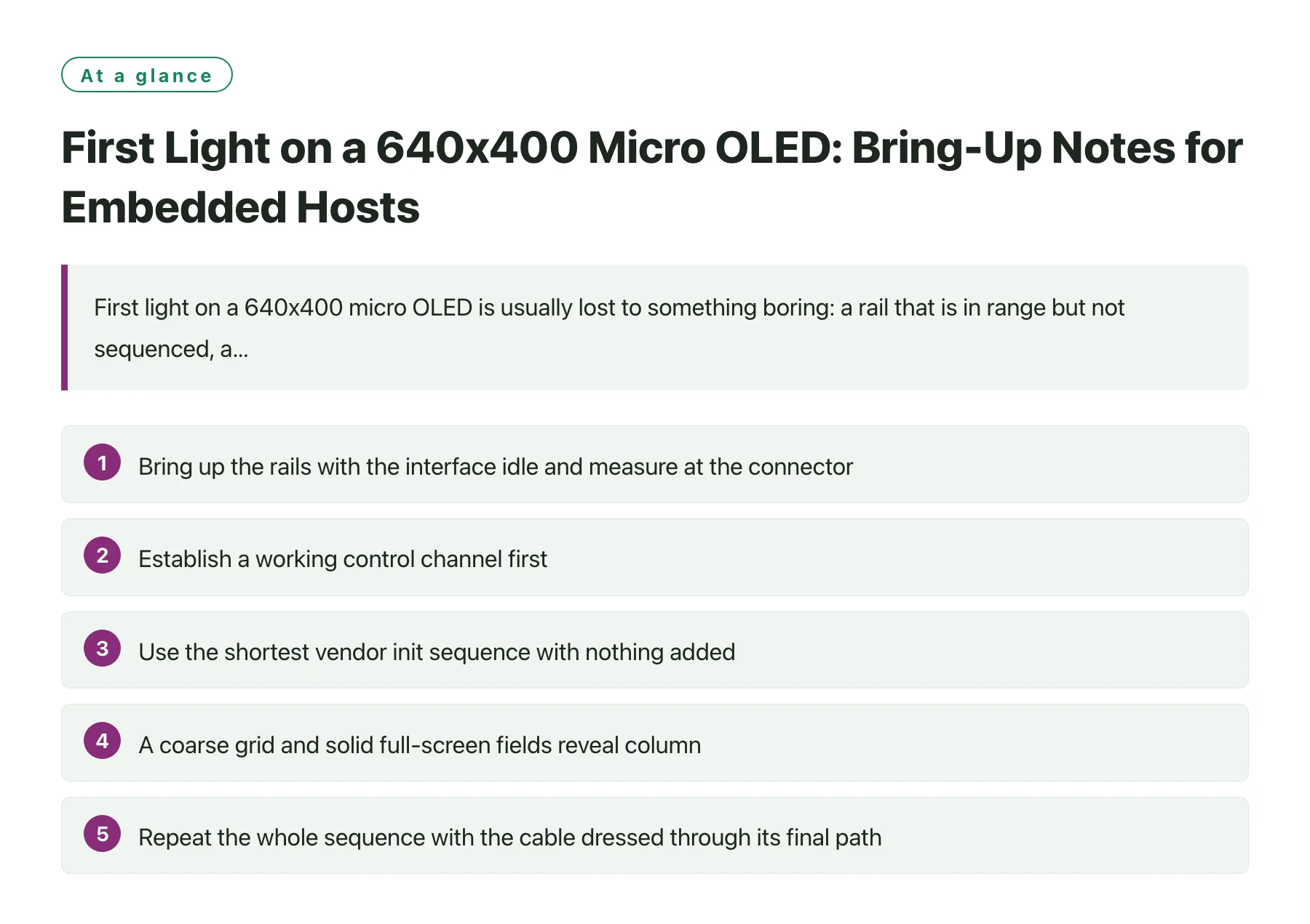
Key takeaways
- Bring up the rails with the interface idle and measure at the connector, not at the regulator, so cable drop is included in what you verify.
- Establish a working control channel first; if you can read one known register back, most of the interface is already proven.
- Use the shortest vendor init sequence with nothing added, because every extra write hides which setting actually mattered.
- A coarse grid and solid full-screen fields reveal column, row and colour-order faults that photographs and gradients hide.
- Repeat the whole sequence with the cable dressed through its final path, since intermittent faults mostly appear only there.
Embedded display bring-up is a search problem with a small number of branches: power, control, configuration and data. Teams that debug all four at once end up changing several things between tests and learning nothing. Teams that freeze three branches and vary one usually finish quickly.
The other habit worth adopting is instrumenting the connection rather than the code. A probe on the panel connector, a logic analyser on the control lines and a current meter on the supply rail will answer most questions faster than print statements added to a driver.
The notes below assume a 0.23-inch 640x400 micro OLED with a 60 Hz refresh, driven from a microcontroller or single-board computer class host. The sequence applies equally to other small panels; only the register names change.
What first light actually requires
Four things have to be true at the same time before a pixel appears: the supplies must be present and correctly sequenced, the reset and control lines must be in their idle states, the panel must have accepted a valid configuration, and the data path must be delivering something the panel can interpret. If any one of them is false the result is the same black screen, which is why the order matters more than the cleverness of the debug.
Sequencing deserves particular attention because it is invisible on a schematic. Many small panels require the logic supply to be stable before the analogue supply rises, or require reset to be held for a defined interval after the last rail settles. A host that powers everything from one regulator output will often appear to work, then fail on a cold start at low temperature. Boards designed around a panel such as the DisplayModule 0.23-inch 640x400 micro OLED are usually documented with the intended order, and it is worth following it exactly even when a shortcut appears to work.
The control channel is your only window into the panel. Before a picture is attempted, read back an identifier or a status register and confirm the value matches the datasheet. That single test distinguishes a wiring fault from a configuration fault, and it costs two minutes.
A bench order that finds faults early
- Check the rails unloaded, then loadedMeasure each supply at the connector with the interface idle, then again with the panel configured. A rail that sags only under load points at the cable or the regulator, not the code.
- Release reset deliberatelyConfirm the reset line actually toggles with a probe. A pull-up that fights the driver, or a line left floating, produces a panel that never leaves its initial state.
- Read a known registerUse the slowest clock you have, read one documented register, and compare against the datasheet value. Do not proceed until this passes.
- Write the minimal init sequenceType in the vendor sequence exactly as published. Resist the urge to add a tweak that a colleague mentioned; you cannot attribute a fix you bundled with three other changes.
- Show a coarse gridA grid of thick lines and a few solid fields exposes missing columns, swapped rows and colour-order errors immediately. A photograph of a face does not.
- Stress the timing and the cableSweep the interface clock across its permitted range and repeat with the flex routed through its final mechanical path. Record where it breaks, not just whether it broke.
Matching the host to the job
| Host class | What it can do directly | What you normally have to add |
|---|---|---|
| 8-bit microcontroller board | Drive a slow serial interface and hold a small framebuffer in RAM [1] | Level shifting, a stable clock source, and realistic expectations about refresh rate while other code runs |
| Single-board computer | Provide a full operating system, mature display stack and enough memory for double buffering [2] | Careful level translation, correct device tree or overlay configuration, and attention to boot ordering |
| 32-bit microcontroller with a display peripheral | Generate a continuous pixel stream without loading the core, and use DMA for transfers | Correct peripheral configuration and a buffer layout the panel's expected format actually accepts |
| Wireless SoC | Run the application and the display from one part, which simplifies the bill of materials | Acceptance that radio activity perturbs timing unless the link and its return paths are designed for it |
| FPGA or soft-core board | Produce exactly the timing the panel asks for, with no software jitter at all | A verified timing generator and a plan for how configuration data reaches the panel at startup |
When the init sequence is all you have
Panel configuration is often published as a register list with little commentary. That is enough to get a picture, but it is worth reading the list as documentation rather than as a script. Registers that set timing parameters tell you the supported pixel clock range. Registers that set supply or bias behaviour tell you the expected power-up order. Registers that select an interface mode tell you which pins are live.
Read the sequence as a dependency graph
Some writes only take effect after another setting has been applied, or after a delay. If the sequence works at room temperature and fails on a cold board, the likely cause is a delay that is shorter than the panel wants. Increasing only those delays is a legitimate fix; reordering writes by guesswork is not.
A useful discipline is to save the exact sequence that produced first light, together with the clock frequency and the supply measurements, as the reference configuration for the project. Every later change is then measured against a known-good baseline.
Keep the driver portable
Write the panel configuration as data, not as code woven through a driver. A table of register writes plus a small number of named parameters survives a change of host far better than a driver full of magic numbers, and it makes it obvious when a colleague has edited one value for a local workaround. When the same product family later moves to a different host or a different panel revision, that table is the only thing that has to be reviewed [3].
Portability also matters for the tooling. Reusable low-level bus helpers, such as an established serial library, mean the panel-specific part of the code stays small enough to review in one sitting [4].
If the panel is dark, resist changing more than one thing per test. The fastest path out is a written list of four branches, power, control, configuration and data, with the first three verified in that order. Nine times out of ten the fault is in the first two, and both can be checked with a probe and a register read before any image code is touched.
Sources
Frequently asked questions
How do I know whether the problem is wiring or configuration?
Try to read a documented register back from the panel. If the read succeeds and returns the expected value, the wiring is good and the fault is in configuration or data. If the read fails or returns garbage, work on the physical link before touching the init sequence.
Should I use the slowest possible interface clock for bring-up?
For the first register access, yes. A slow clock is far more tolerant of long jumper leads and imperfect grounding, and getting a working control channel matters more than speed at that stage. Raise the clock later, once a picture is on screen, so you can tell when it starts to break.
Why does the panel work on the bench but fail in the enclosure?
Because the enclosure changes the electrical environment. Flex routed through a hinge adds length and changes the return path, and nearby radios add common-mode noise. Repeat the full bring-up sequence with the cable in its final position; the difference between the two runs usually points straight at the cause.
How important is the power-up sequence for a small micro OLED?
It is easy to ignore and expensive to get wrong. If the panel specifies an order for its rails and a reset delay, follow it. Symptoms of getting it wrong are intermittent and temperature-dependent, which makes them very hard to attribute later in the project.